The purpose of this exercise is to observe the relationship between the magnitude of the induced EMF and the applied magnetic field
At the end of this exercise you will have:
• Used appropriate methods for measuring the induced voltage as a function of current, frequency, and angle.
• Plotted correctly drawn graphs and determined the required quantities.
Introduction
A magnetic field, which varies with time, is generated by passing a current through a short coil of wire (for this experiment, two short coils pushed together with a small gap between them). A “search coil” is placed on the axis in the centre of the two coils. Since the magnetic field is varying, an EMF is induced in the search coil. Figure 1.
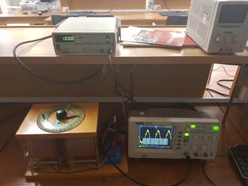
Experimental setup, showing the large coils, the search coil, signal generator, and the oscilloscope.
For this experiment you will vary the current, the frequency of generated signal, and the angle of the search coil and determine the induced voltage. Varying these three variables you will confirm the relationship between εo and Io εo and ω εo and θ Equation 3 
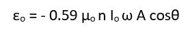
where ω is equal to 2πf
μo = permeability constant = 4π × 10-7 Hm-1 n = number of turns/unit length = 37,777 turns/m for each of the large coils provided
I = current in the coil in Amperes (the same in both large coils)
ω = is directly proportional to the frequency of the input signal f (Hz)
A = cross-sectional area of the search coil 9.5 x 10⁻⁵m2
θ = the angle between the large coils and the search coils
Select the parameters of the experiment, default is 1 mA, 100 Hz, 0o
Current (mA)
Frequency (Hz)
Angle (θ o)
Measurments
Current Current is mA
Current Frequency is Hz
Current Angle is o
Induced Voltage is μV
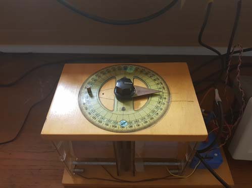
  The experimental setup
Measurment
1
2
3
4
5
6
7
Mass
Force
Object length vs Image Screen Length
When you do the experiment in the lab remember that you are not measuring ε0 or I0 but; E0 = 480 ε0 × 1500 and V0=1000*I0